the 'BrrBot'
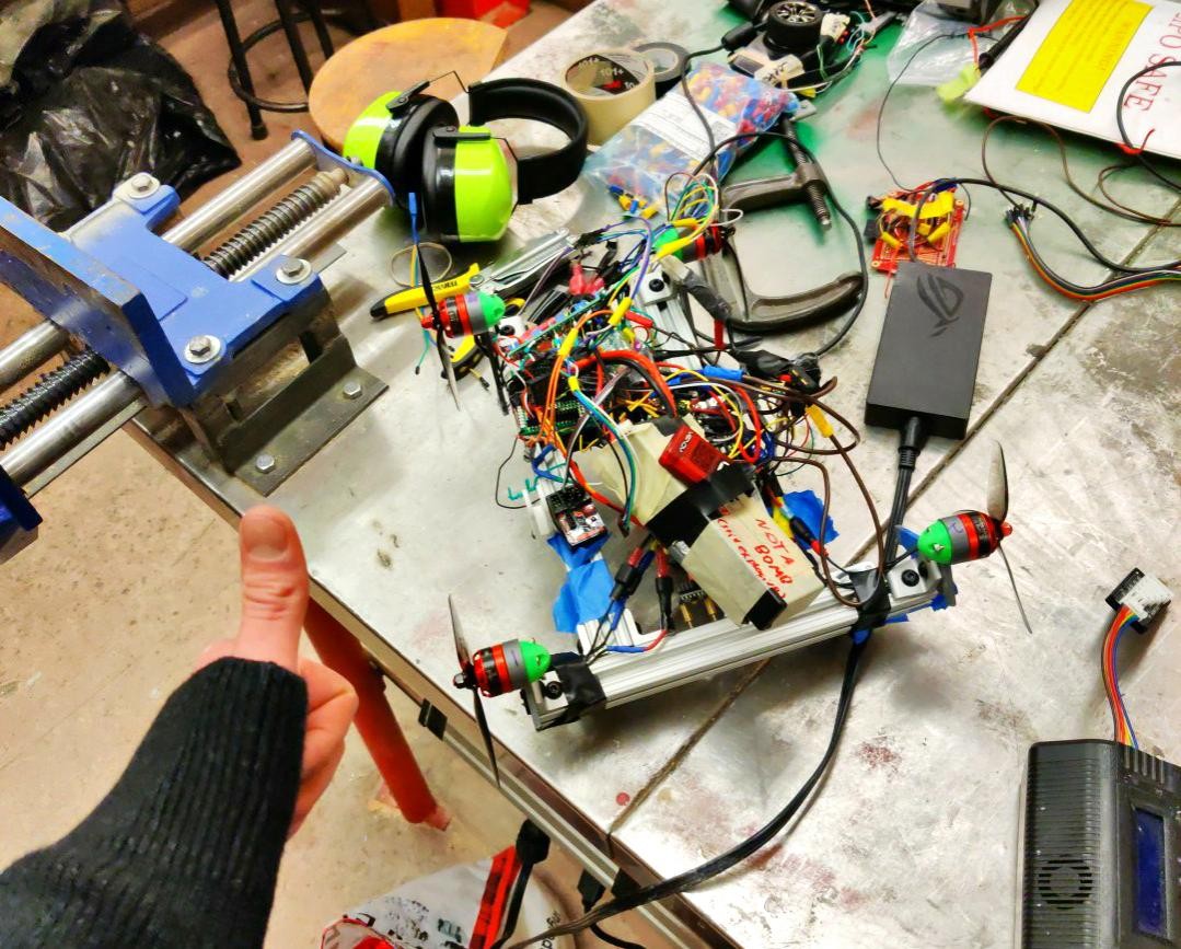
Safety glasses are required for this one...
What I'm most proud of:
My detailed journey:
This is my project writeup for my line following robot for an introductory engineering design class (IGEN 230). We were supposed to use a kit that came with all the components , any ways I deviated from the original design was intended to make this harder for me.
This was a tedious, challenging and fun engineering adventure. I started out trying to make a balancing motorcycle robot, and ended with a robot that uses fans to turn.
Please note that as my robot looks different, and does use more powerful motors, I spent a lot of time and effort into this project. Any ways I deviated from the original design was intended to make this harder for me. I kept to an Arduino Nano for the whole project. This was the first project where I created a sketch that was too big to load onto a Nano.
After a couple weeks of prototyping the motorcycle, I decided to scrap that idea and go down to 1 wheel. Now begins the 'self balancing wheelbarrow' design.
I made the thrust of the drone motors dependent on the robot's position. I created a feedback loop using an accelerometer to measure the position. I was able to balance the robot, but as soon as it would drive forward or back, the shock to angular momentum and the inertia of the robot caused the robot to fall immediately.
This was where the fun really began, as I realized the Nano was too slow to accelerate the stepper motor to reduce the angular acceleration shock.
So I put this to the side, but I'm excited to return to the wheelbarrow design once I figure out PID control and have some spare time. I found an Arduino library that calculates PID with integers, using no floating point math, so I may be able to do it off an Arduino Uno or Nano!
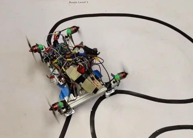
My next design consisted of 4 PWM driven drone motors, facing perpendicular to the robot, and I added 2 swivel wheels so it would be constrained along the Y axis, making the control a lot easier.
A stepper motor controls movement in the forward/back, but the robot is free moving around the angular Z direction. The fans are what control the turning.
I also had to add a beefy 2s LiPo battery to support the (up to) 80A draw of the drone motors. (I'm guessing they average about half of this, but they also stalled during high acceleration and quick turns. My LiPo can supply up to 175 amps continuous, so I'm guessing the lipo drops voltage at high burst currents. The battery is like 3 years old.)
Sadly, a 2s lipo only gets to like 8.4V when fully charged, and the stepper driver needs at least 9V. So I have one 2s Lipo and another NiMH to provide over 10 V to the stepper driver. This also made it safer to test the robot, as I could independently power the fans or the stepper motor depending on what I was testing.
I used a RC controller to test it, but the Nano could only read 2 inputs because it only has 2 interrupt pins. If you are wondering if I cheated and controlled the robot to follow the line, it's clear in the video that the receiver is not connected to the remote due to the red status light.
This setup actually worked quite well due to the sensors positioned at the pivot point of the robot. This means that the sensor position is very responsive to the pivot of the robot. Also, the fans naturally can only accelerate or decelerate the robot's angular momentum, producing more natural and gradual changes to it's trajectory. Using 2 powered wheels with simple code means the wheels IMMEDIATLEY adjust the angular acceleration of the robot. This causes movements to be pretty jagged, and especially because the original design places the sensors in front of the robot's pivot point, making them pivot faster than the robot pivots. If your robot's trajectory is dependent on IR sensors and the line, then the information that the IR sensors read should be the most 'important' information to the robot, in my opinion, the line underneath the pivot point of the robot. I used 2 sensors to complete course one. I'm aiming to complete all the courses with only 2 sensors as I want to understand why its impossible/possible to run the harder courses with 2 sensors.
Also, it's simpler to make sure the robot actually pivots, so when the robot is turning, the powered wheel is stationary.
NEXT PROBLEM! The Nano wasn't fast enough to read the IR sensors and drive the stepper motor. So I slowed down the sensor readings to only read once every 20 times the code runs.
NEXT PROBLEM! The robot is coded to always go forward and power the fans. How am I going to safely disconnect the batteries so the thousands of RPM doesn't hurt me?
My kill switch was based on the position of the accelerometer. Picking the robot up and dipping it down cuts power to the fans. Also, running this off a Nano was actually a little dangerous, as the drone motors keep the speed of the last command, and don't need to be constantly driven like the stepper motor does. So if the Nano malfunctions when the fans are running, they will keep running and the kill switch will not work. I can make this safer by having an independent kill switch that uses a relay to cut power.